

0
Owner's of the American Audio DJ Equipment Pro Scratch 1 gave it a score of 0 out of 5. Here's how the scores stacked up:

“Q” series mixers.
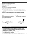
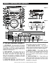
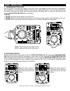
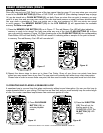
35.DIGITAL OUT - Use this connection to create
near perfect copies of your disc to a Mini disc,
CD-R, or any other digital recording device.
36. HEADPHONE MONITOR - Use this stereo
jack to connect a pair of headphones.
37. HEADPHONE VOLUME CONTROL - This
knob will control the volume output level of the
HEADPHONE JACK (36).
38.VOLTAGE SELECTOR - Because power sup-
plies vary from location to location we have
incorporated a selectable power supply. This
switch can select a voltage input of 115V or
230V. Always disconnect the power plug before
changing the voltage.
39.POWER CONNECTOR - This connection is
used to connect your main power. Be sure that
your local power matches the unit’s required
power.
40.POWER SWITCH - This switch is used to
turn your unit’s power on and off.
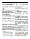
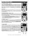
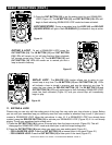
C. FRONT PANEL (FIGURE 5)
41. CD SLOT POWER INDICATOR - This is the
main power LED. This extremely bright Indigo
LED will also aid in locating the CD slot in dark
and club situations.
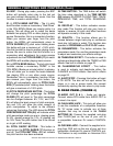
D. LCD DISPLAY (FIGURE 6)
42. PLAY INDICATOR - This indicator will glow
when the unit is in play mode.
43. EFFECT INDICATOR - This will glow when
any of the four built-in effects are selected.
44.SINGLE INDICATOR - This indicates that the
CD drive is in single play mode, the track will
play once and return to CUE mode. If the single
indicator is not on the unit is in continuous mode
In continuous mode the drive will play all the
remaining tracks on the disc. Once the remaining
tracks have ended the unit will return to cue
mode
45. LOOP - This icon will flash when you are in
loop mode. This icon will glow when a loop has
been created but is not actively playing.
46. RELOOP INDICATOR - Appears when LOOP
is engaged or ready to be engaged.
47. PAUSE INDICATOR - This indicator will glow
when the drive is in pause mode.
48.TRACK INDICATOR - This indicator describes
which track is currently cued or is playing.
49.CUE INDICATOR - This indicator will glow
when the unit is in CUE or mode and will flash
every time a new CUE POINT is set.
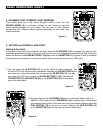
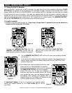
50, 51, 52. TIME METERS - These indicators will
detail the current Minutes, Seconds, and Frames.
The meter will display either the elapse, total,
or remaining time of a track or the entire disc.
The display time will depend on the selected
time function. The selected time function will be
displayed above the TIME METER as TOTAL
REMAIN (57), REMAIN (57) OR ELAPSE (58).
53. MEMORY BUCKET INDICATOR - This indi-
cates serves two functions. The red bucket outline
details the cue memory status, a full bucket
outline indicates the cue memory is full. The five
bars in the memory bucket detail the anti-shock
memory state. Each bar indicates 2 second of
digital anti-shock
54.BPM/PITCH METER - This meter will display
either the BPM's or pitch percentage applied by
the PITCH SLIDER (17). The meters definition
will be indicated by either BPM or PITCH (55).
55.TIME BAR INDICATOR - This bar gives a
visual approximation of a track's or disc's time
This bar will begin to flash when a track is ending.
The flashing bar is great reminder, that time is
running out to get that next track ready to go.
56.TOTAL/REMAIN INDICATOR - When TOTAL
is indicated in the LCD DISPLAY (1) the TIME
DESCRIBED (50, 51, & 52) in the LCD will define
the total disc remaining time. When REMAIN
is indicated in the LCD DISPLAY (1) the TIME
DESCRIBED (50, 51, & 52) in the LCD will define
the current track's remaining time.
57.ELAPSE INDICATOR - When this indicator is
on it will define the time displayed in the TIME
METER (50, 51, & 52) as the current track’s
elapse time.
GENERAL FUNCTIONS AND CONTROLS (Cont.)
American DJ® AUDIO •Pro Scratch 1™ INSTRUCTION MANUAL • PAGE 9


Find Your Products By Category
Please Login
